Visualising cardiac simulations with Cmgui
Cmgui is a powerful visualization tool that has several key features that make it unique:
- It is scriptable, i.e., you can feed it with a series of text instructions and Cmgui will simply print out the images you require.
- It allows for visualization of moving meshes, which makes it very useful for mechanics simulations.
- The images produced are always somewhat better looking than other visualizers.
On the other hand, using Cmgui is not as intuitive as, for example, Meshalyzer.
The best place to start is the Cmgui examples page. In particular, it is advisable to start with the first one: viewing a cube. At any point in time, it is often useful to consult the full list of cmgui commands.
Basic usage of the graphical front end after a Chaste simulation
Chaste is capable of outputting Cmgui-readable files containing the solution of the simulation. Since mastering Cmgui may take some time, Chaste also outputs a little script called LoadSolutions.com that makes the user skips the first steps of reading the mesh from file and loading up the data. The Chaste Cmgui output is located within a directory called cmgui_output. After running a Chaste simulation, the best thing to do is to go to that cmgui_output directory and type
PATH_TO_CMGUI_EXECUTABLE LoadSolutions.com
where PATH_TO_CMGUI_EXECUTABLE refers to the place where you put your cmgui executable. This will pop up the graphics and command windows as shown here
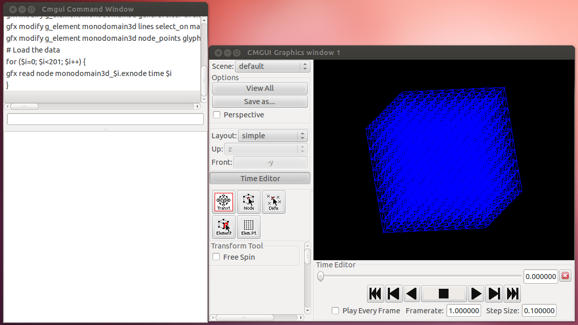
Within the graphic window
- Left-click and move --> Rotate object
- Right-click and move up --> Zoon-out
- Right-click and move down --> Zoom-in
Note that the instruction above loaded the geometry AND the data. It is instructive to give a look at the script and see the PERL-style syntax of Cmgui.
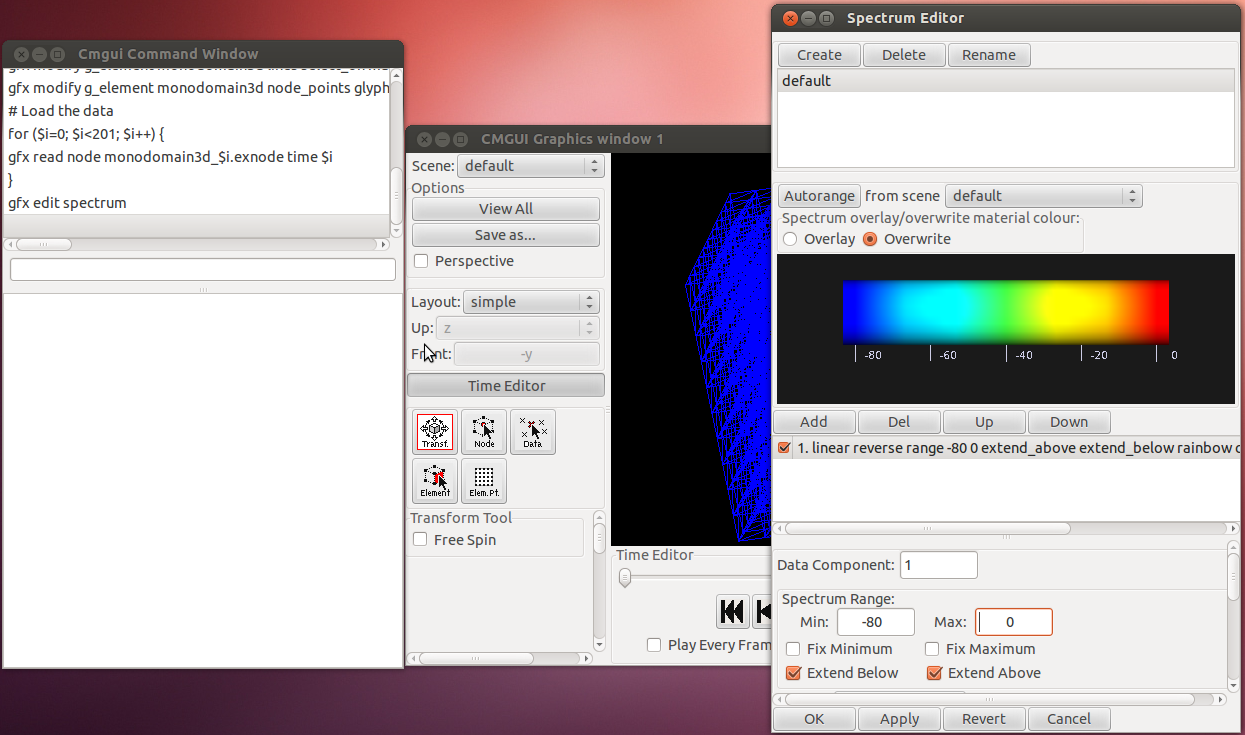
If you want to change the spectrum, select Graphic-->Spectrum editor. Here you can adjust the spectrum minimum and maximum as shown here
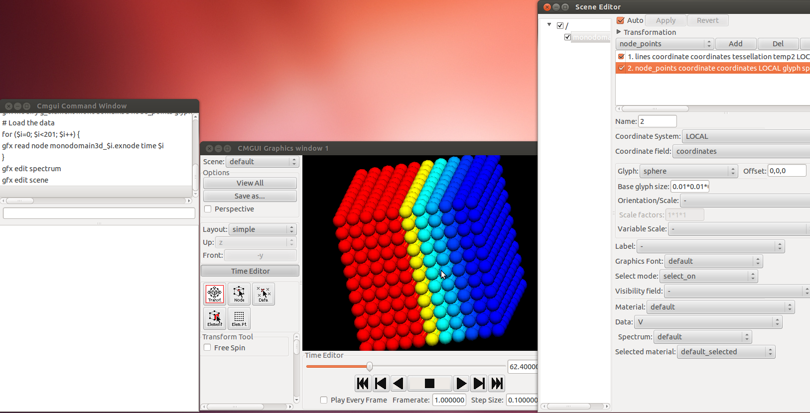
Another very useful window is Scene Editor which you can bring up by choosing Graphic-->Scene editor. ehre you can manipulate what you see and how. In the example below, I choose to visualize my nodes as little spheres
More advanced usage using Cmgui scripts
As mentioned above, one of the most powerful features of Cmgui is that you can feed a script to it and Cmgui will just print the image you like. The syntax of the script is a Perl-like syntax. All Cmgui commands have the structure of gfx COMMAND_NAME options. Comments are preceded by the # character.
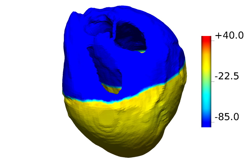
Here, we will comment an example of a script that was used for a published figure.
We start by reading in the mesh. We will issue 2 read commands, one for nodes and one for elements, followed by the path to the node and element files respectively. We then define the faces so that we can plot a surface. In this example, monodomain3d is the name of the group used in the Chaste simulation.
# Read the mesh
gfx read node MyocytesPlusFibroblasts/cmgui_output/extended1d.exnode
gfx read elem MyocytesPlusFibroblasts/cmgui_output/extended1d.exelem
gfx define faces egroup monodomain3d
Now we load the data, which is conatained in a .exnode file. There will be one of these files per time step of simulation.
# Load the data
gfx read node MyocytesPlusFibroblasts/cmgui_output/extended1d_140.exnode
An alternative is to read ALL time steps in one go by means of a for loop (in this case we have 200 time steps):
for ($i=0; $i<201; $i++) {
gfx read node extended1d_$i.exnode time $i
}
Then we create a graphical window:
# Create a window
gfx create window 1 double_buffer;
and then adjust our preferred view. You can choose your view by playing with the mouse and when you are happy with it, you can issue a command (in the cmgui command window)
gfx list window 1 commands
The output can be copied and pasted in our script so that next time the very same angle, point of view, etc will be re-created exactly. An example of an output is
gfx modify window 1 image scene default light_model default;
gfx modify window 1 image add_light default;
gfx modify window 1 layout simple ortho_axes z -y eye_spacing 0.25 width 1715 height 1125;
gfx modify window 1 set current_pane 1;
gfx modify window 1 background colour 0 0 0 texture none;
gfx modify window 1 view parallel eye_point 8.58981 3.21216 5.66403 interest_point 1.18447 1.10423 1.46629 up_vector -0.502462 0.0458483 0.863383 view_angle 26.953 near_clipping_plane 0.0876946 far_clip$
gfx modify window 1 set transform_tool current_pane 1 std_view_angle 40 normal_lines no_antialias depth_of_field 0.0 fast_transparency blend_normal;
Similar consideration apply for the spectrum. You can play with the graphical interface until you are happy with it and then, in the CMgui command window, issue a command
gfx list spectrum default commands
copy and paste the output in the script. In our example, the output will look like
gfx modify spectrum default clear overwrite_colour;
gfx modify spectrum default linear reverse range -85 40 extend_above extend_below rainbow colour_range 0 1 component 1;
The following instructions are used to make the spectrum appear on your image
#put the spectrum in...
gfx cre scene overlay
gfx mod scene overlay add_light default
gfx mod win 1 overlay scene overlay
gfx create colour_bar spectrum default
gfx cre colour_bar as colour_bar axis 0 1 0 centre 1 0 0 divisions 2 font BIG length 1 number_format %+.1f label_material black tick_direction 1 0 0

gfx draw colour_bar scene overlay position 0
The following instructions are obtained with the command
gfx list g_element XXXX commands
and are the ones that specify the nature of your graphical elements (e.g, nodes as spheres, lines hidden or showing, surface hidden or showing, etc)
gfx modify g_element extended1d general clear circle_discretization 6 default_coordinate coordinates element_discretization "4*4*4" native_discretization none;
gfx modify g_element extended1d lines select_on invisible material default data Vm_1 spectrum default selected_material default_selected;
gfx modify g_element extended1d node_points glyph point general size "1*1*1" centre 0,0,0 font default select_on invisible material default data Vm_1 spectrum default selected_material default_selected;
gfx modify g_element extended1d surfaces select_on material default data Vm_1 spectrum default selected_material default_selected render_shaded;
Finally, we print the output
gfx print postscript file myo_plus_fibro.eps win 1
The full script we just discussed is
# Read the mesh
gfx read node MyocytesPlusFibroblasts/cmgui_output/extended1d.exnode
gfx read elem MyocytesPlusFibroblasts/cmgui_output/extended1d.exelem generate_faces_and_lines
# Load the data
gfx read node MyocytesPlusFibroblasts/cmgui_output/extended1d_140.exnode

# Create a window
gfx create window 1 double_buffer;
gfx modify window 1 image scene default light_model default;
gfx modify window 1 image add_light default;
gfx modify window 1 layout simple ortho_axes z -y eye_spacing 0.25 width 1715 height 1125;
gfx modify window 1 set current_pane 1;
gfx modify window 1 background colour 0 0 0 texture none;
gfx modify window 1 view parallel eye_point 8.58981 3.21216 5.66403 interest_point 1.18447 1.10423 1.46629 up_vector -0.502462 0.0458483 0.863383 view_angle 26.953 near_clipping_plane 0.0876946 far_clip$
gfx modify window 1 set transform_tool current_pane 1 std_view_angle 40 normal_lines no_antialias depth_of_field 0.0 fast_transparency blend_normal;

# SPECTRUM
gfx modify spectrum default clear overwrite_colour;
gfx modify spectrum default linear reverse range -85 40 extend_above extend_below rainbow colour_range 0 1 component 1;

gfx define font BIG "50 default normal normal"

#put the spectrum in...
gfx cre scene overlay
gfx mod scene overlay add_light default
gfx mod win 1 overlay scene overlay
gfx create colour_bar spectrum default
gfx cre colour_bar as colour_bar axis 0 1 0 centre 1 0 0 divisions 2 font BIG length 1 number_format %+.1f label_material black tick_direction 1 0 0


gfx draw colour_bar scene overlay position 0

# Modify the scene (obtained by gfx list g_element XXXX commands)
gfx modify g_element extended1d general clear circle_discretization 6 default_coordinate coordinates element_discretization "4*4*4" native_discretization none;
gfx modify g_element extended1d lines select_on invisible material default data Vm_1 spectrum default selected_material default_selected;
gfx modify g_element extended1d node_points glyph point general size "1*1*1" centre 0,0,0 font default select_on invisible material default data Vm_1 spectrum default selected_material default_selected;
gfx modify g_element extended1d surfaces select_on material default data Vm_1 spectrum default selected_material default_selected render_shaded;

#Print the output
gfx print postscript file myo_plus_fibro.eps win 1

quit
Results of the script above, i.e, the file myo_plus_fibro.eps looks like