This tutorial was generated from the file projects/Microvessel/test/tutorials/TestBuildVesselNetworkLiteratePaper.hpp at revision r27242. Note that the code is given in full at the bottom of the page.
Building A Vessel Network Tutorial
This tutorial is designed to introduce the C++ interface for modelling vessel networks.
The following is covered:
- Manually building a network from a collection of nodes, segments and vessels
- Managing dimensions and units
- Reading, writing and visualizing vessel networks
- Vessel network generators
The Test
Start by introducing the necessary header files. The first contain functionality for setting up unit tests.
#include <cxxtest/TestSuite.h>
#include "AbstractCellBasedWithTimingsTestSuite.hpp"
Boost shared pointers are used extensively in this component. This header contains some useful pointer MACROs.
#include "SmartPointers.hpp"The OutputFileHandler manages where output files are written to.
#include "OutputFileHandler.hpp"These headers contain the building-blocks of the vessel networks; nodes, segments, vessels and the network itself.
#include "VesselNode.hpp"
#include "VesselSegment.hpp"
#include "Vessel.hpp"
#include "VesselNetwork.hpp"
Tools for reading and writing networks.
#include "VesselNetworkReader.hpp"
#include "VesselNetworkWriter.hpp"
Dimensional analysis.
#include "DimensionalChastePoint.hpp"
#include "UnitCollection.hpp"
#include "BaseUnits.hpp"
Tools for automatically generating vessel networks
#include "VesselNetworkGenerator.hpp"Used to initialize MPI/PETSc in unit tests.
#include "PetscSetupAndFinalize.hpp"Tutorials are developed as a series of unit tests using the CxxTest framework. Make a single test class, which inherits from
AbstractCellBasedWithTimingsTestSuite. AbstractCellBasedWithTimingsTestSuite adds some useful functionality to the default
CxxTest::TestSuite class, including setting up timers and initializing random number generators.
class TestBuildVesselNetworkLiteratePaper : public AbstractCellBasedWithTimingsTestSuite
{
public:
Test 1 - Building a vessel network manually, writing it to file and visualizing it

In the first test build a vessel network from its constituent components; nodes, segments and vessels. Do some simple tests to make sure the network has been formed as expected. Then write the network to file and visualize it in Paraview. The network will be built manually, which is tedious and not done much in practice. Later examples will used automatic generators.
    void TestBuildNetworkManually() throw (Exception)
    {
First, a note on units. In many simulations with vessel networks care is needed in managing units, as multiple computational grids and
physical phenomena are of interest. It is helpful to be explicit regarding assumed length, time and mass scales and to specify input parameters
with accompanying units. In this component, the DimensionalChastePoint is a fundamental geometric feature which contains a location in N
dimensional space, stored as a vector of dimensionless doubles, and an accompanying reference length. Thus, each DimensionalChastePoint is a
location with units. To demonstrate, we will create a point, which has a reference length of 1 micron and then re-scale its location according
to a different reference length, a cell width. Note that the syntax reference_length(1.0 * unit::microns) rather than
reference_length = 1.0 * unit::microns is used when instantiating quantities.
        units::quantity<unit::length> reference_length(1.0 * unit::microns);
        DimensionalChastePoint<2> my_point(25.0, 50.0, 0.0, reference_length);
We can use the unit test framework to check our coordinate values are assigned as expected.
        TS_ASSERT_DELTA(my_point[0], 25.0, 1.e-6);
        TS_ASSERT_DELTA(my_point[1], 50.0, 1.e-6);
If we want our coordinates in terms of a fictitious cell width unit we just have to rescale the reference length.
        units::quantity<unit::length> cell_width(25.0 * unit::microns);
        my_point.SetReferenceLengthScale(cell_width);
        TS_ASSERT_DELTA(my_point[0], 1.0, 1.e-6);
        TS_ASSERT_DELTA(my_point[1], 2.0, 1.e-6);
It is tedious to keep supplying a reference length, mass, time when setting up simulations. To avoid this a BaseUnits singleton is
used to set these values. Any geometrical features, readers, writers, solvers etc. created after a base unit has been set will take
the current value as their ReferenceXScale. As will be demonstrated, these values can be over-ridden on a class-by-class basis
if needed.
        BaseUnits::Instance()->SetReferenceLengthScale(reference_length);
        BaseUnits::Instance()->SetReferenceTimeScale(60.0 * unit::seconds);
All geometric features, VesselNodes, Parts, RegularGrids use the DimensionalChastePoint as their base representation of spatial
location, meaning that it is straight-forward to change or even mix length scales in a simulation.
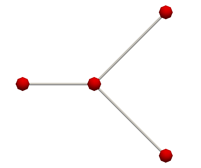
Now we proceed to making some nodes, which are point features from which vessels can be constructed. They are initialized in the same way as
a DimensionalChastePoint, but use a convenience Create factory method to get a shared pointer. We will create a 2D Y shaped network.
Again, we will avoid the tedium of manual network creation in later examples.
        double vessel_length = 100.0;
        boost::shared_ptr<VesselNode<2> > p_node_1 = VesselNode<2>::Create(0.0, 0.0);
        boost::shared_ptr<VesselNode<2> > p_node_2 = VesselNode<2>::Create(vessel_length, 0.0, 0.0, reference_length);
        boost::shared_ptr<VesselNode<2> > p_node_3 = VesselNode<2>::Create(2.0*vessel_length, vessel_length);
        boost::shared_ptr<VesselNode<2> > p_node_4 = VesselNode<2>::Create(2.0*vessel_length, -vessel_length);
Next make vessel segments and vessels. Vessel segments are straight-line features which contain a VesselNode at each end. Vessels
can be constructed from multiple vessel segments by adding them in order, but in this case each vessel just has a single segment.
        boost::shared_ptr<VesselSegment<2> > p_segment_1 = VesselSegment<2>::Create(p_node_1, p_node_2);
        boost::shared_ptr<Vessel<2> > p_vessel_1 = Vessel<2>::Create(p_segment_1);
        boost::shared_ptr<VesselSegment<2> > p_segment_2 = VesselSegment<2>::Create(p_node_2, p_node_3);
        boost::shared_ptr<Vessel<2> > p_vessel_2 = Vessel<2>::Create(p_segment_2);
        boost::shared_ptr<VesselSegment<2> > p_segment_3 = VesselSegment<2>::Create(p_node_2, p_node_4);
        boost::shared_ptr<Vessel<2> > p_vessel_3 = Vessel<2>::Create(p_segment_3);
Now add the vessels to a vessel network.
        boost::shared_ptr<VesselNetwork<2> > p_network = VesselNetwork<2>::Create();
        p_network->AddVessel(p_vessel_1);
        p_network->AddVessel(p_vessel_2);
        p_network->AddVessel(p_vessel_3);
Use the test framework to make sure that the network has been created correctly by checking the number of vessels and nodes
        TS_ASSERT_EQUALS(p_network->GetNumberOfNodes(), 4u);
        TS_ASSERT_EQUALS(p_network->GetNumberOfVessels(), 3u);
Next write the network to file. Use the OutputFileHandler functionality to manage the output location
and the pointer MACRO MAKE_PTR_ARGS to easily make a smart pointer. Networks are written using VTK’s PolyData format by default,
which will have a .vtp extension.
        MAKE_PTR_ARGS(OutputFileHandler, p_handler, ("TestBuildVesselNetworkLiteratePaper"));
        VesselNetworkWriter<2> writer;
        writer.SetFileName(p_handler->GetOutputDirectoryFullPath() + "bifurcating_network.vtp");
        writer.SetVesselNetwork(p_network);
        writer.Write();

        BaseUnits::Instance()->Destroy();
    }
Now we can visualize then network in Paraview. See the tutorial here, to get started. To view the network import the file
TestBuildVesselNetworkLiteratePaper\bifurcating_network.vtp into Paraview. For a nicer rendering you can do Filters->Alphabetical->Tube.
Test 2 - Building a vessel network using a generator and reading from file

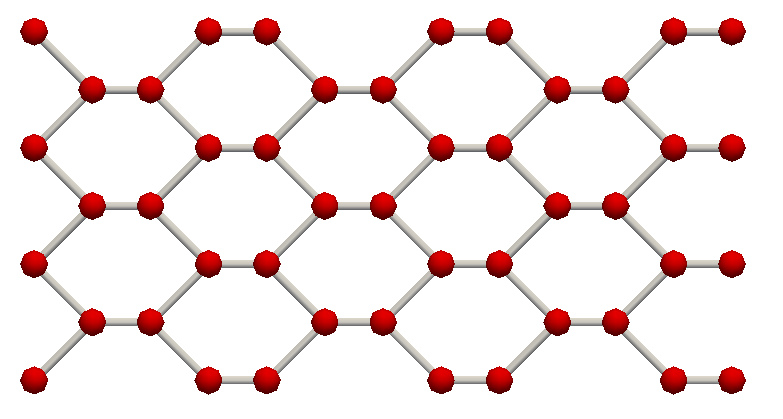
It is usually tedious to build a vessel network from scratch. In this test we use a generator to automatically construct a network. We then write it to file, read it back in and check that it is restored as expected.
    void TestBuildNetworkFromGeneratorAndReadFromFile() throw (Exception)
    {
Create a hexagonal network in 3D space using a generator. Specify the target network width and height and the desired vessel length. The use of dimensional analysis is demonstrated by now using a fictitious ‘cell width’ reference length unit instead of microns.
        units::quantity<unit::length> cell_width(25.0 * unit::microns);
        BaseUnits::Instance()->SetReferenceLengthScale(cell_width);
        BaseUnits::Instance()->SetReferenceTimeScale(60.0 * unit::seconds);
        units::quantity<unit::length> target_width = 60.0 * cell_width;
        units::quantity<unit::length> target_height = 30.0 * cell_width;
        units::quantity<unit::length> vessel_length = 4.0 * cell_width;
Note that the generator is given the reference length scale. This is not imperative, but helps to ensure that all point coordinates are stored with the same reference length scale. This is helpful when combining with computational grids and cell populations later on.
        VesselNetworkGenerator<3> network_generator;
        boost::shared_ptr<VesselNetwork<3> > p_network = network_generator.GenerateHexagonalNetwork(target_width,
                                                                                                    target_height,
                                                                                                    vessel_length);
Get the number of nodes and vessels for testing later, and write the network to file as before. We want to over-ride the reference length scale so that the output is written in micron. We could also change the ‘ReferenceLengthScale’ in ‘BaseUnits’ if we wanted.
        unsigned number_of_nodes = p_network->GetNumberOfNodes();
        unsigned number_of_vessels = p_network->GetNumberOfVessels();
        MAKE_PTR_ARGS(OutputFileHandler, p_handler, ("TestBuildVesselNetworkLiteratePaper", false));
        VesselNetworkWriter<3> writer;
        writer.SetFileName(p_handler->GetOutputDirectoryFullPath() + "hexagonal_network.vtp");
        writer.SetVesselNetwork(p_network);
        units::quantity<unit::length> micron_length_scale(1.0*unit::microns);
        writer.SetReferenceLengthScale(micron_length_scale);
        writer.Write();
Use a reader to read the network back in from the VTK file. Our network was written in units of micron, so we need to tell the reader this so that locations are suitably stored.
        VesselNetworkReader<3> network_reader;
        network_reader.SetReferenceLengthScale(micron_length_scale);
        network_reader.SetFileName(p_handler->GetOutputDirectoryFullPath() + "hexagonal_network.vtp");
        boost::shared_ptr<VesselNetwork<3> > p_network_from_file = network_reader.Read();
Finally we check that the network has been correctly read back in using our unit test framework
        TS_ASSERT_EQUALS(p_network_from_file->GetNumberOfNodes(), number_of_nodes);
        TS_ASSERT_EQUALS(p_network_from_file->GetNumberOfVessels(), number_of_vessels);
    }
It is suggested that the tutorial on flow modelling is covered next.
};Code
The full code is given below
File name TestBuildVesselNetworkLiteratePaper.hpp
#include <cxxtest/TestSuite.h>
#include "AbstractCellBasedWithTimingsTestSuite.hpp"
#include "SmartPointers.hpp"
#include "OutputFileHandler.hpp"
#include "VesselNode.hpp"
#include "VesselSegment.hpp"
#include "Vessel.hpp"
#include "VesselNetwork.hpp"
#include "VesselNetworkReader.hpp"
#include "VesselNetworkWriter.hpp"
#include "DimensionalChastePoint.hpp"
#include "UnitCollection.hpp"
#include "BaseUnits.hpp"
#include "VesselNetworkGenerator.hpp"
#include "PetscSetupAndFinalize.hpp"
class TestBuildVesselNetworkLiteratePaper : public AbstractCellBasedWithTimingsTestSuite
{
public:
    void TestBuildNetworkManually() throw (Exception)
    {
        units::quantity<unit::length> reference_length(1.0 * unit::microns);
        DimensionalChastePoint<2> my_point(25.0, 50.0, 0.0, reference_length);
        TS_ASSERT_DELTA(my_point[0], 25.0, 1.e-6);
        TS_ASSERT_DELTA(my_point[1], 50.0, 1.e-6);
        units::quantity<unit::length> cell_width(25.0 * unit::microns);
        my_point.SetReferenceLengthScale(cell_width);
        TS_ASSERT_DELTA(my_point[0], 1.0, 1.e-6);
        TS_ASSERT_DELTA(my_point[1], 2.0, 1.e-6);
        BaseUnits::Instance()->SetReferenceLengthScale(reference_length);
        BaseUnits::Instance()->SetReferenceTimeScale(60.0 * unit::seconds);
        double vessel_length = 100.0;
        boost::shared_ptr<VesselNode<2> > p_node_1 = VesselNode<2>::Create(0.0, 0.0);
        boost::shared_ptr<VesselNode<2> > p_node_2 = VesselNode<2>::Create(vessel_length, 0.0, 0.0, reference_length);
        boost::shared_ptr<VesselNode<2> > p_node_3 = VesselNode<2>::Create(2.0*vessel_length, vessel_length);
        boost::shared_ptr<VesselNode<2> > p_node_4 = VesselNode<2>::Create(2.0*vessel_length, -vessel_length);
        boost::shared_ptr<VesselSegment<2> > p_segment_1 = VesselSegment<2>::Create(p_node_1, p_node_2);
        boost::shared_ptr<Vessel<2> > p_vessel_1 = Vessel<2>::Create(p_segment_1);
        boost::shared_ptr<VesselSegment<2> > p_segment_2 = VesselSegment<2>::Create(p_node_2, p_node_3);
        boost::shared_ptr<Vessel<2> > p_vessel_2 = Vessel<2>::Create(p_segment_2);
        boost::shared_ptr<VesselSegment<2> > p_segment_3 = VesselSegment<2>::Create(p_node_2, p_node_4);
        boost::shared_ptr<Vessel<2> > p_vessel_3 = Vessel<2>::Create(p_segment_3);
        boost::shared_ptr<VesselNetwork<2> > p_network = VesselNetwork<2>::Create();
        p_network->AddVessel(p_vessel_1);
        p_network->AddVessel(p_vessel_2);
        p_network->AddVessel(p_vessel_3);
        TS_ASSERT_EQUALS(p_network->GetNumberOfNodes(), 4u);
        TS_ASSERT_EQUALS(p_network->GetNumberOfVessels(), 3u);
        MAKE_PTR_ARGS(OutputFileHandler, p_handler, ("TestBuildVesselNetworkLiteratePaper"));
        VesselNetworkWriter<2> writer;
        writer.SetFileName(p_handler->GetOutputDirectoryFullPath() + "bifurcating_network.vtp");
        writer.SetVesselNetwork(p_network);
        writer.Write();

        BaseUnits::Instance()->Destroy();
    }
    void TestBuildNetworkFromGeneratorAndReadFromFile() throw (Exception)
    {
        units::quantity<unit::length> cell_width(25.0 * unit::microns);
        BaseUnits::Instance()->SetReferenceLengthScale(cell_width);
        BaseUnits::Instance()->SetReferenceTimeScale(60.0 * unit::seconds);
        units::quantity<unit::length> target_width = 60.0 * cell_width;
        units::quantity<unit::length> target_height = 30.0 * cell_width;
        units::quantity<unit::length> vessel_length = 4.0 * cell_width;
        VesselNetworkGenerator<3> network_generator;
        boost::shared_ptr<VesselNetwork<3> > p_network = network_generator.GenerateHexagonalNetwork(target_width,
                                                                                                    target_height,
                                                                                                    vessel_length);
        unsigned number_of_nodes = p_network->GetNumberOfNodes();
        unsigned number_of_vessels = p_network->GetNumberOfVessels();
        MAKE_PTR_ARGS(OutputFileHandler, p_handler, ("TestBuildVesselNetworkLiteratePaper", false));
        VesselNetworkWriter<3> writer;
        writer.SetFileName(p_handler->GetOutputDirectoryFullPath() + "hexagonal_network.vtp");
        writer.SetVesselNetwork(p_network);
        units::quantity<unit::length> micron_length_scale(1.0*unit::microns);
        writer.SetReferenceLengthScale(micron_length_scale);
        writer.Write();
        VesselNetworkReader<3> network_reader;
        network_reader.SetReferenceLengthScale(micron_length_scale);
        network_reader.SetFileName(p_handler->GetOutputDirectoryFullPath() + "hexagonal_network.vtp");
        boost::shared_ptr<VesselNetwork<3> > p_network_from_file = network_reader.Read();
        TS_ASSERT_EQUALS(p_network_from_file->GetNumberOfNodes(), number_of_nodes);
        TS_ASSERT_EQUALS(p_network_from_file->GetNumberOfVessels(), number_of_vessels);
    }
};